Gary Anderson's verdict on F1's late final 2024 car
Williams should be in a better place going into the 2024 Formula 1 season.
Team principal James Vowles has had a year to put in place aspects of the structure and procedures that made his previous employer Mercedes so successful. With the addition of Pat Fry as chief technical officer, Williams should go from being a little lost to having a positive direction.
Now, all it has to do is ensure it doesn’t get too ambitious on the way.
It needs to make sure it hangs onto Alex Albon in the long-term because other teams will soon start to make noises about poaching him. In the short term, the number two driver must collect points. Logan Sargeant has the speed, but last year made too many mistakes.
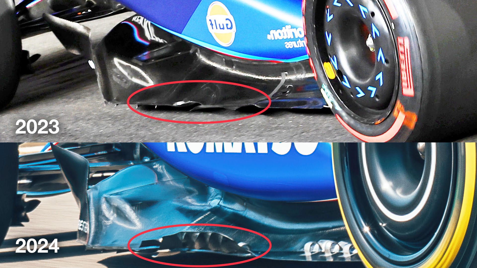
Williams was one of the teams that very early on in 2023 followed the visual concept of the Red Bull. The car has always been fast on the straights, which unfortunately usually points to a lack of downforce. But the drivers have generally complained about a lack of front grip and brake locking into slow corners.
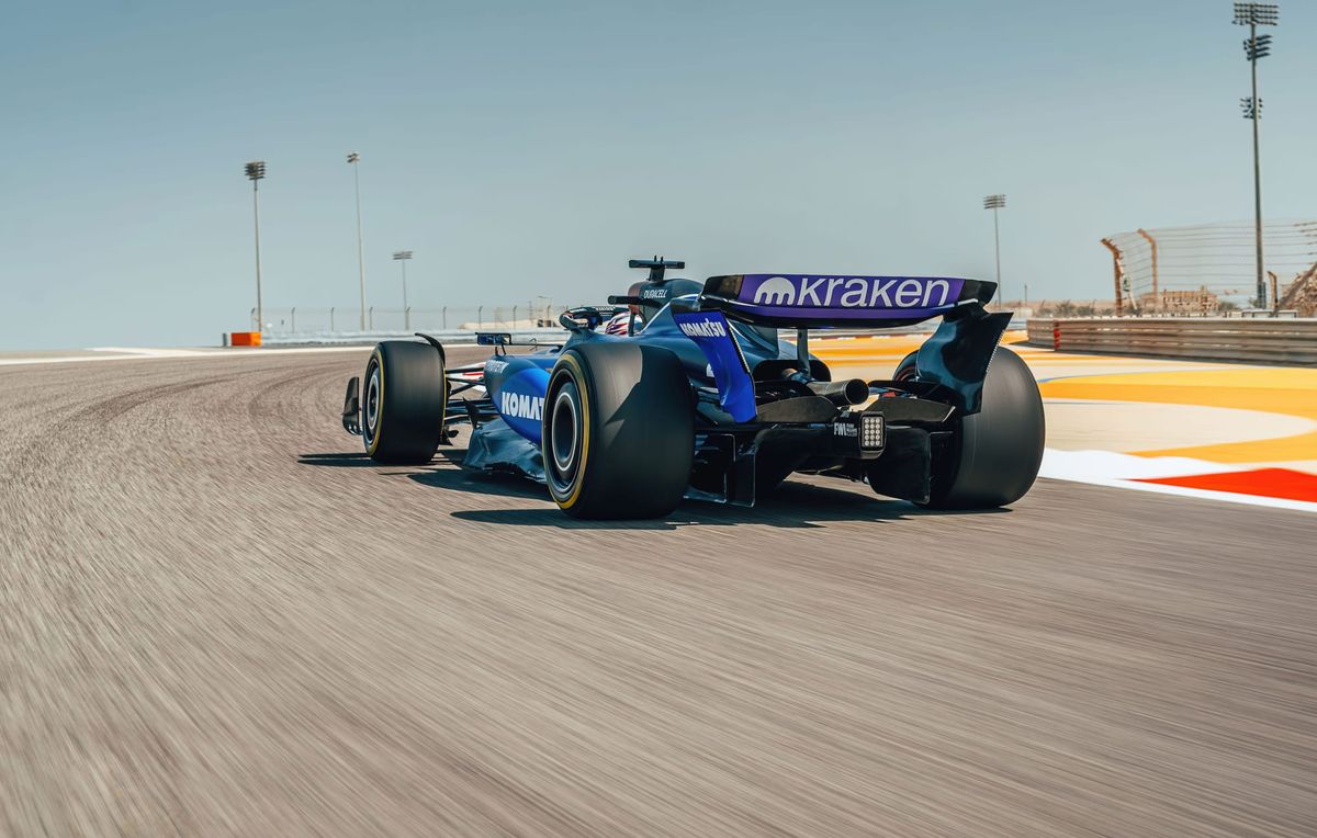
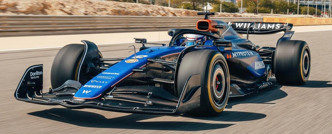
Williams is the last team to reveal its 2024 car, doing so in a shakedown in Bahrain the day before testing starts.
As with most of the cars we have seen so far this year, Williams has taken inspiration from the 2023 Red Bull template. It all looks neat and tidy, but is it enough to move the team into the top 10 consistently?
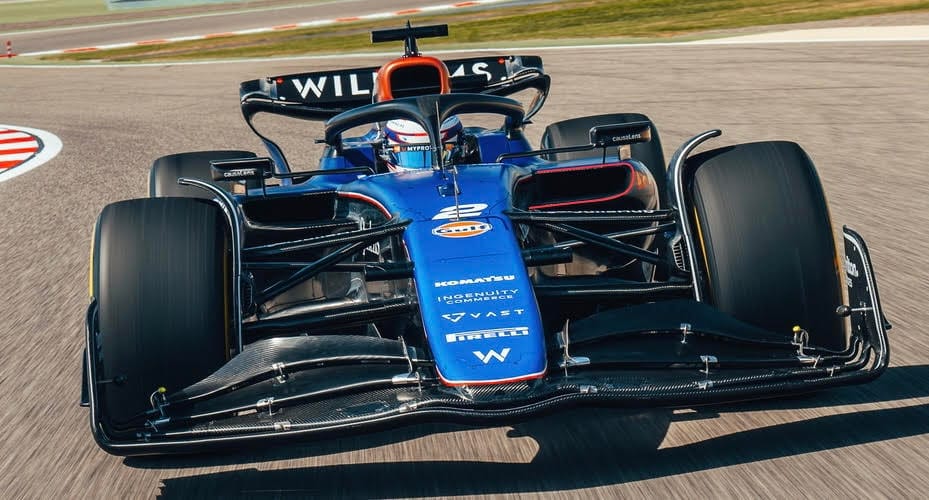
NOSE/FRONT WING
The nose and front wing assembly has changed subtly from what Williams ran last year. The car now has a slot gap underneath the nose area between the leading element and the second element (red highlight below). This will help with flow attachment on the underside of the nose.
The nose has a square and flatter upper surface, which means less of the flow will go around the sides of the nose. With this design, more will go over the top surface (yellow arrows in the image below). As we can see, the wing section close to the nose (orange ellipse) will receive less high energy airflow, so that means it’s effectively less powerful.
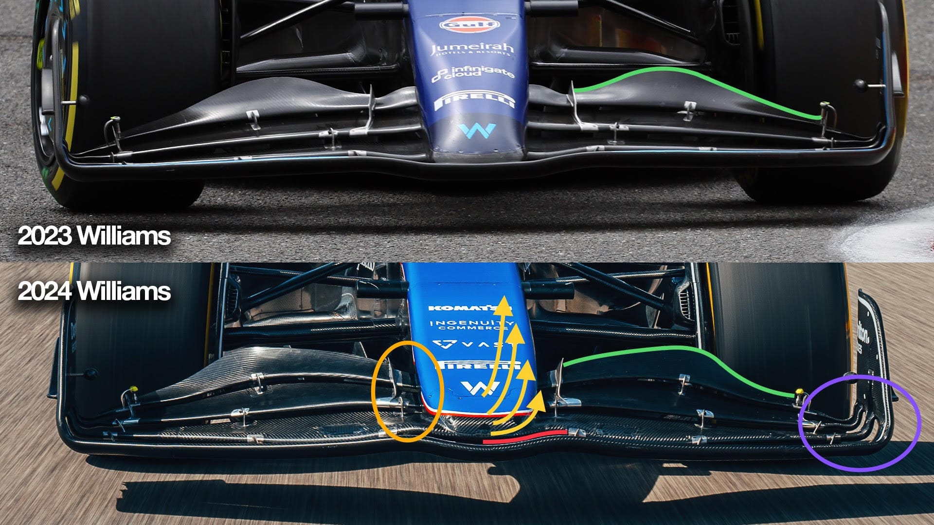
The profile of the trailing edge of the fourth element (green highlights above) has changed to alter the load distribution across the front wing span. The load is now more uniform and increases as it goes outboard. The longest chord section is just inside the inner corner of the front tyre, but I would worry a little about the effect the tyre will have on front aero load when steering lock is applied.
The outboard end where the flaps meet the end plate (magenta ellipse above) is all about maximising the outwash in this area. Connecting the airflow coming off the upper and lower surfaces using these outer slot gaps to the airflow that is displaced outwards when the tyre rotates on the track surface means that less airflow is displaced inboard, reducing the inboard turbulence. This, in turn, will improve the performance of the leading edge of the underfloor.
FRONT SUSPENSION
The front suspension layout is again similar to last year, with a pushrod-operated inboard torsion spring and damper (red highlight below).
The upper assembly (dark green forward leg, light green rear leg above and below) has the customary but possibly increased anti-dive, which is shown by the height difference where the inboard ends meet the chassis.
There seems to be more of a height difference on the outboard end, leading me to think that what we normally call the upper wishbone is in fact a multi-link. In other words, two separate components.
With this, you can place the outer pick-ups to give you reduced camber change with increased steering lock. In slow corners, the lateral ‘g’ is much less than in the fast corners so reducing the camber with high steering angles increases the front tyre contact patch, which should increase front grip.
Again, looking from behind we can see this height difference (yellow ellipse below) on the outboard ends.
SIDEPOD INLET
Williams was the first to follow the Red Bull inlet style in 2023, so it’s no surprise that it has continued down that route.
The inlets are nowhere near as much of a letterbox shape as Red Bull finished last season with, but that might just be to do with the Mercedes power unit heat rejection compared to the Honda and/or Williams cooling technology relative to Red Bull.
Maximum efficiency in both those areas can pay big dividends as airflow used for cooling is not much use to generate downforce.
AIRBOX INTAKE
The airbox intake area is interesting. Most teams have adopted the triangular inlet, but Williams has gone more square.
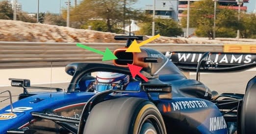
It looks like the separation of the inlet is horizontal (green arrow), with the lower flow (red arrow) going to the turbo and the upper section (yellow arrow) feeding some of the cooling requirements.
Structurally for the rollover bar requirements this is just a little more difficult but it also allows the lower surface to be that little bit higher, which reduces turbulence and allows for taller drivers.
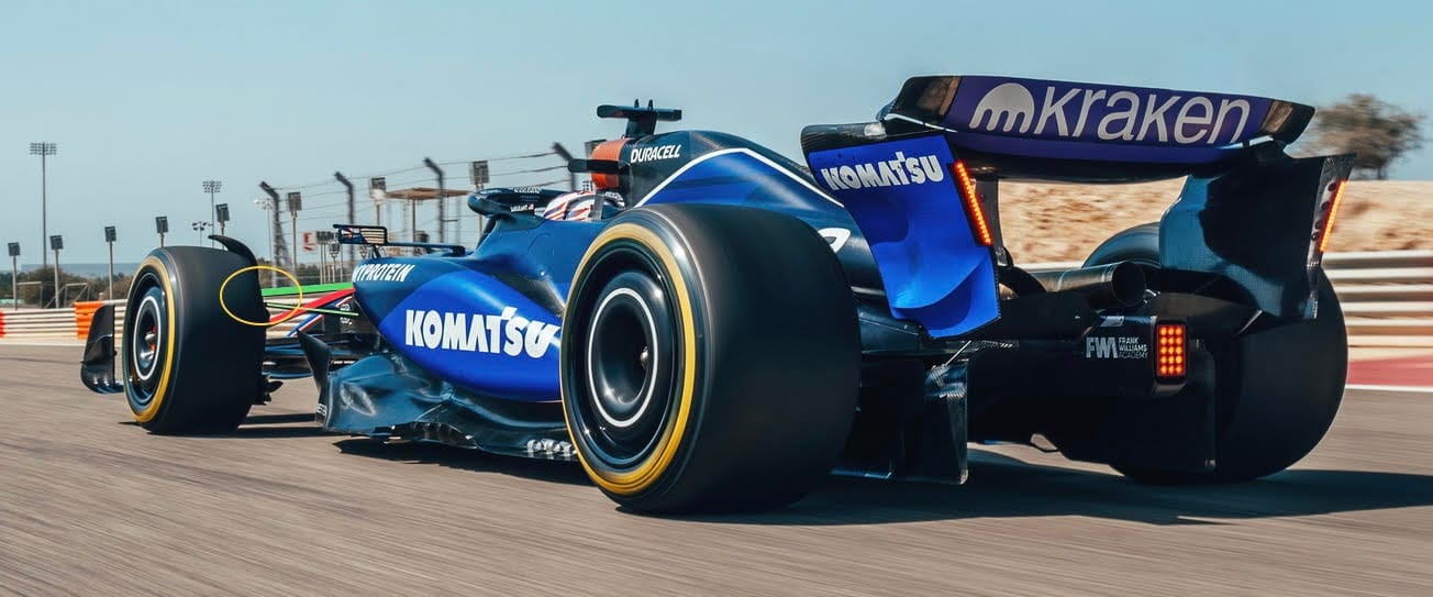
FLOOR EDGE
Moving down the side of the car, we can see that treatment of the floor edge (red ellipse below) is much more aggressive than previously.
Williams has really focused on scavenging the airflow out from under the forward corner of the underfloor.
This allows the diffuser to work mainly on the airflow coming in under the nose area to the central part of the underfloor.
The airflow on the outer edge of the floor is critical to the performance of the underfloor and diffuser.
The yellow arrows in the image below represent the flow coming over the upper surface. I have also highlighted a slot gap that is between the main underfloor surface and the outer edge surface. These two are separated to allow flow through this area to set up the sealing vortices.
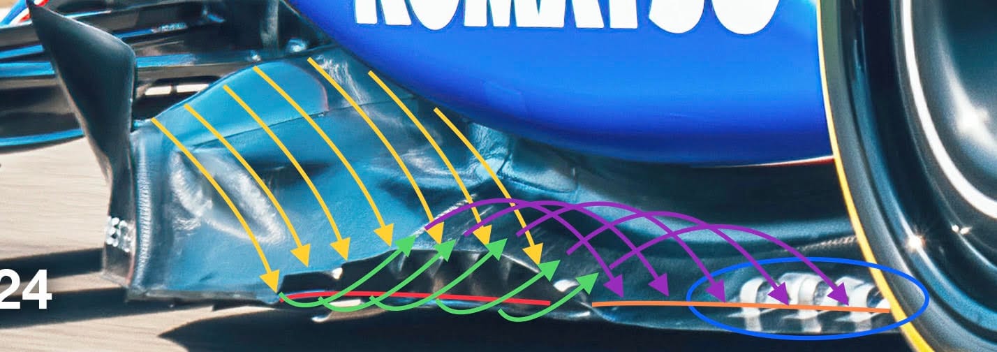
The upper surface flow (yellow arrows above) will go through that forward section of the slot gap (red highlight). This pulls the flow from underneath the front corner of the floor (green arrows).
This will then set up an airflow rotation (magenta arrows) which will go back through the slot gap (orange highlight) and if it all goes to plan connect up with the airflow displaced by the rear tyre rotating onto the track surface. The aim is for this to go outside of the tyre, keeping it away from the diffuser.
The blue ellipse above highlights what I would call the hangers that support that longitudinal outer edge section. It’s easy for these to ‘burst’ the vortices that you have so carefully generated, so attention to detail here is critical.
REAR END
The rear suspension is largely dictated by Mercedes given Williams uses its gearbox. The inboard pick-up points will be defined by Mercedes, so even if Williams makes its own suspension the basic geometry will be very similar.
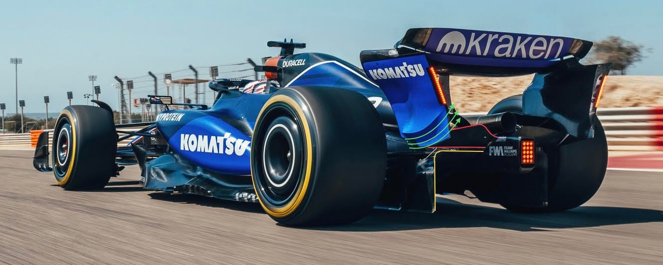
In this rear corner shot it has used the beam wing (red highlight above) to improve the performance of the diffuser (yellow highlight). This will be an item that will change depending on circuit downforce requirements, but when you need high levels of downforce then getting the airflow at the rear of the car to work as one is much more powerful than them all working independently.
Even the feature on the outer surface of the wing endplate (green arrows) is there to influence the airflow on that surface, which again will influence the airflow across the complete back of the car.
CONCLUSION
It’s all getting a bit more like a one-make formula. Paint them all the same colours and it might just take a couple of guesses before you could say who is who.
That said, it is the smaller details that will make the difference in performance. Together with the piece we don’t see - the underfloor - we go into pre-season testing with no idea who will have used the winter to make progress.
Not everyone is going to be fastest, but it would be nice if the overall pack closed up just a little bit giving us some hope of a bit of result variety.
With testing proper in Bahrain on Wednesday, 2024 starts now!