Gary Anderson's verdict on Mercedes W15 and its front wing quirk
After two years of underachievement by its own lofty standards, is 2024 the year Mercedes turns it around and gets back to its pre-ground effect regulations winning ways?
James Allison is back at the helm as technical director, bringing with him the stabilising influence that seems to get the best out of people. That’s all well and good, but you still need to recognise where your problems originate from and rectify the situation.
From my point of view, Mercedes has had difficulty because it prioritised out-and-out peak downforce rather than downforce that is actually usable by the driver - all racing cars need to be driver-friendly.
It’s the old saying ‘once bitten, twice shy’, and if a car has peaky downforce it leads to inconsistent performance. You can get it right occasionally and it looks great, but more often than not it leads to difficult weekends.
So let’s have a look at what Mercedes has learned after two years with only one win. All the usual caveats apply as I can only talk about what we can see, and in certain cases, we have only limited angles and/or slightly misleading digital renders to go on.
COCKPIT POSITION
Lewis Hamilton’s request for a different cockpit position got a lot of attention last year but it couldn’t be changed until now.
It’s very difficult to put an actual number on it but we are pretty sure that on this car Mercedes has moved the driver’s seating position rearwards, probably somewhere between 5-10 centimetres.
Hamilton didn’t like where he was sitting last year because he couldn’t feel the rear axle grip level and grip consistency early enough. This lack of feeling can lead to the rear end being very snappy and more importantly lead to faster degradation of the rear tyres.
FRONT WING
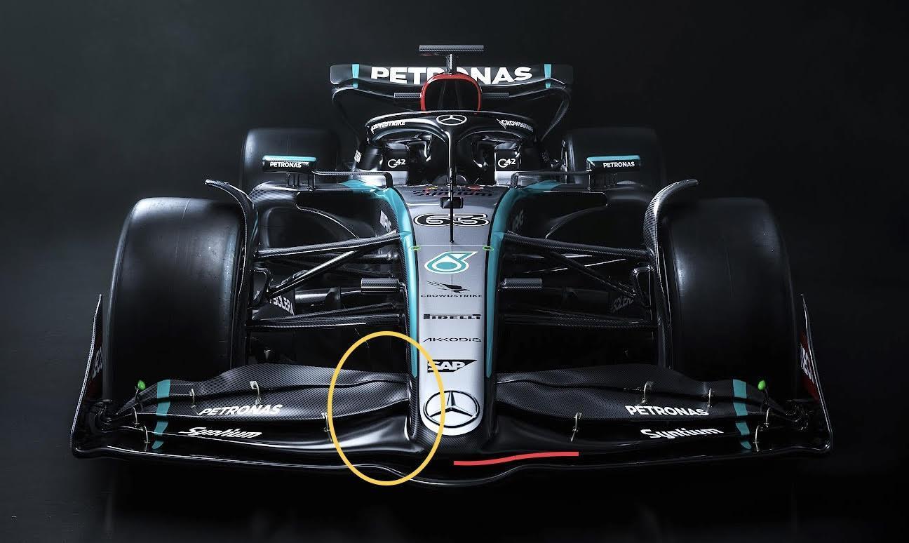
Starting from the front, we can see from this render the new car’s front wing is visually quite different. The inboard end of the flap assembly is more ‘swoopy’ and Mercedes has removed the steps in the profiles as they go outboard (yellow ellipse on the image above).
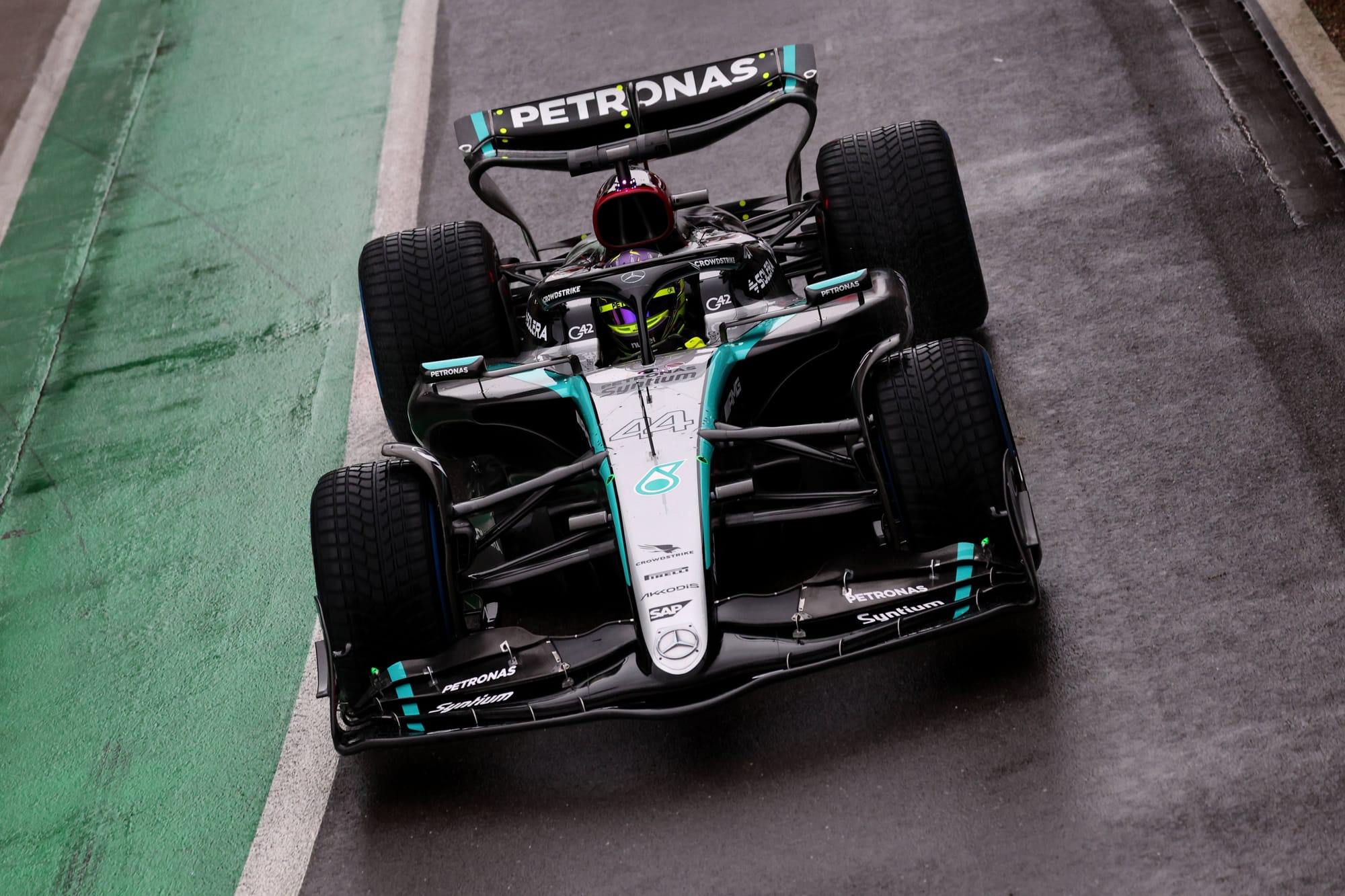
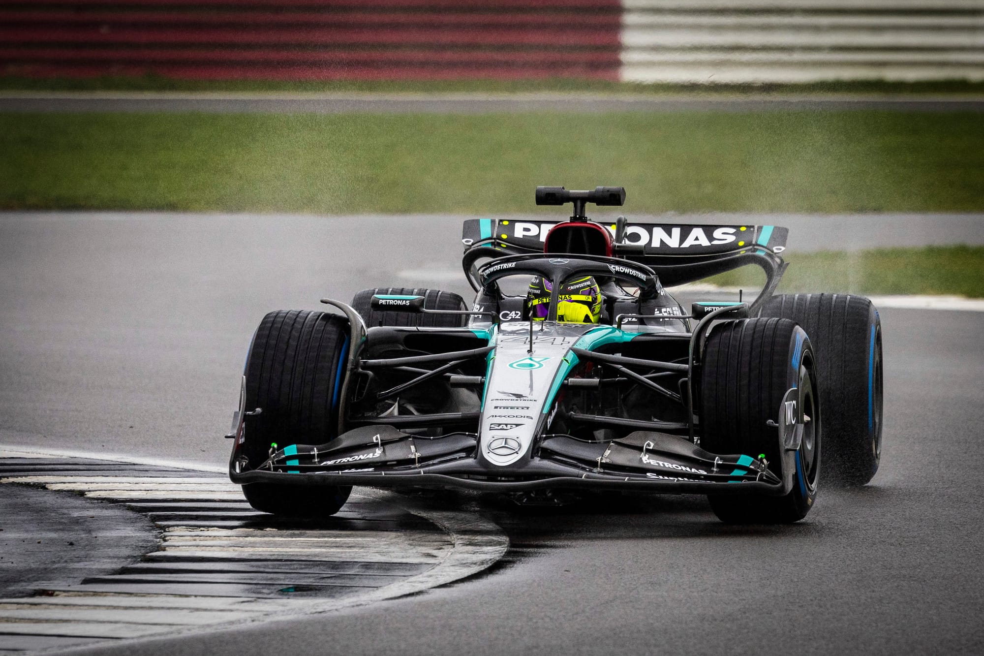
It’s also worth comparing this early rendering of the new Mercedes front wing with some real car images captured from its Silverstone shakedown.
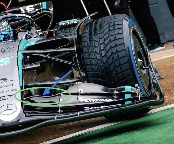
In the picture below, which is of the real car in the garage at Silverstone, it is a bit more difficult to see the detail, but the treatment of the inboard end (green ellipse) of the front wing’s rearmost flap looks quite different.
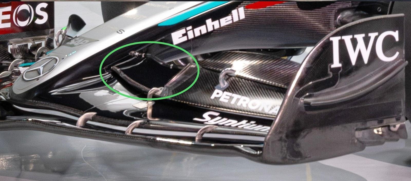
And when the car was driven out onto the track we saw it in more detail (green ellipse, below).

Below are the relevant front wing regulations. I have highlighted in bold italics the sections that might apply to what Mercedes is doing here.
3.9 Front Wing (FW)
3.9.1 Front Wing Profiles
Bodywork declared as “Front Wing Profiles” must lie within RV-FW-PROFILES.
In any Y plane, the following conditions apply:
a. There must be no more than four closed sections.
b. No closed section may contain any concave radius of curvature less than 50mm
c. The distance between adjacent sections must lie between 5mm and 15mm at their closest position.
d. The rearmost point of every closed section must be visible when viewed from below.
e. With the exception of the rearmost closed section, the rearmost point of every closed section must not be visible when viewed from above.

This round section (blue arrow, above) with a slot gap to the third element should comply with the 5-15mm distance rule (and will not be flow-sensitive).
It connects the fourth flap to the nose and covers the trailing edge of the third flap when viewed from above, so I think Mercedes is covering itself on the ‘visible when viewed from above’ rule too.
I don’t see it as a big thing and fairly easy to copy - if there is any benefit. The aim will be to get cleaner airflow to the front of the chassis.
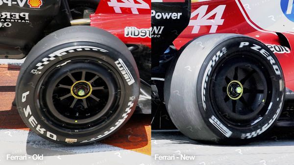
SHORTER NOSE
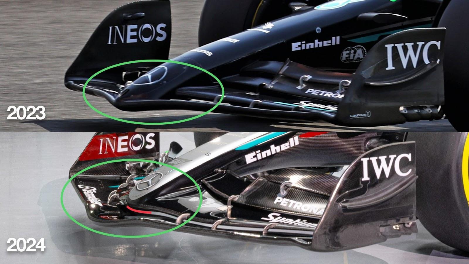
This comparison shows Mercedes has managed to achieve this leading-edge flap slot gap by getting the nose a bit shorter (green ellipse), and by doing that, it separates the underside of the nose from the most forward element of the front wing.
This is a positive, as this slot gap allows more flow through to the underside of the nose and in turn the central section of the leading edge of the underfloor.
FRONT SUSPENSION
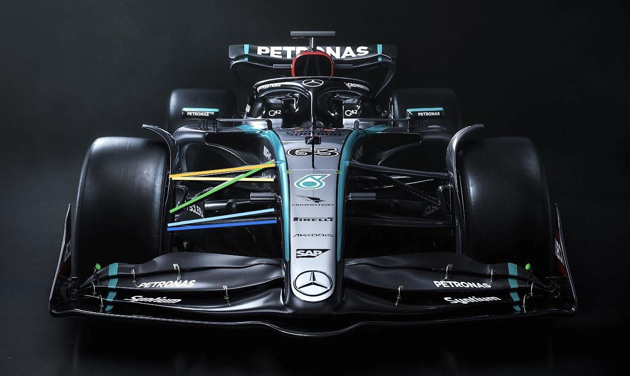
Mercedes has stuck with a similar pushrod operated (green highlight) inboard torsion spring system, and the top wishbone forward leg (dark yellow highlight), rearward leg (light yellow highlight) anti-dive package that first appeared in Monaco last year.
The lower wishbone assembly is fairly flat in its inboard mounting position, but it’s difficult to tell with the angle of the picture. If anything, the rear leg inboard mounting (light blue highlight) could be just that little bit higher than the forward leg inboard mounting (dark blue highlight), giving a little more anti-dive to the complete system.
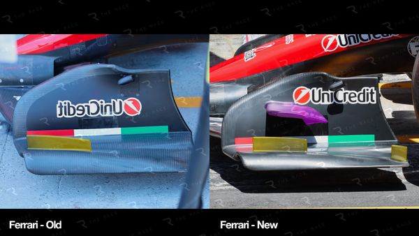
SIDEPOD INLET
This has been the standout visual difference between the Mercedes and the Red Bull for the past two seasons and it would take eating a lot of humble pie to simply copy what Red Bull has set as the standard inlet system for these ground-effect regulations.
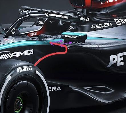
What Mercedes now has (shown in the red highlight above) is on the way to what Red Bull came up with, but not fully committed. Actually, I think it is quite a neat solution.
The radiator duct inlet, and in turn its exit, is about getting the airflow required through the radiator to match the cooling requirement from the power unit and all its ancillaries, plus the hydraulics and the gearbox. Achieving this with the minimum negative on the downforce levels, and downforce consistency, is no easy task.
It’s easy to fool yourself and underestimate what is actually required, but when you get to the circuit you will have to get the jigsaw out and open up a few holes if you have. So it is better design-wise to have extra cooling and then blank off as required.
Comparing the inlet systems from last year and this year, inside the red ellipse above we can see there is a massive difference in the flow that can get through the sidepod undercut.
The inlet still takes some of its airflow from the side of the chassis, but that’s no bad thing as it’s very inboard of the requirement of that undercut flow on the outer edge of the floor.
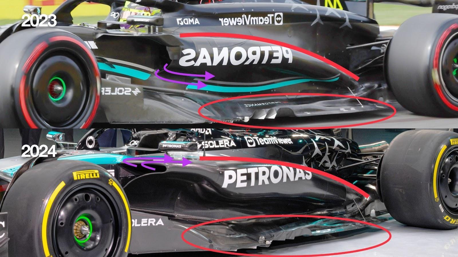
Looking at this side view comparison, we can see what would have happened to the radiator spillage (magenta arrows) last year compared to what I would expect to happen this year.
This will improve the downforce characteristics and consistency between low and high speed.
Further down the sidepod and the floor edge (red ellipse, above) nothing has really changed there ‘yet’.
It’s still early days, and again the underfloor is the powerful component in producing the downforce levels and consistency of downforce that the drivers need to be competitive, so I doubt very much if this is the underfloor we will see in Bahrain. I’m sure something theoretically better is already in the pipeline.
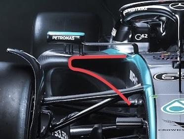
The top surface profile (red highlight, above) of the sidepod is also similar to last year’s end-of-season version.
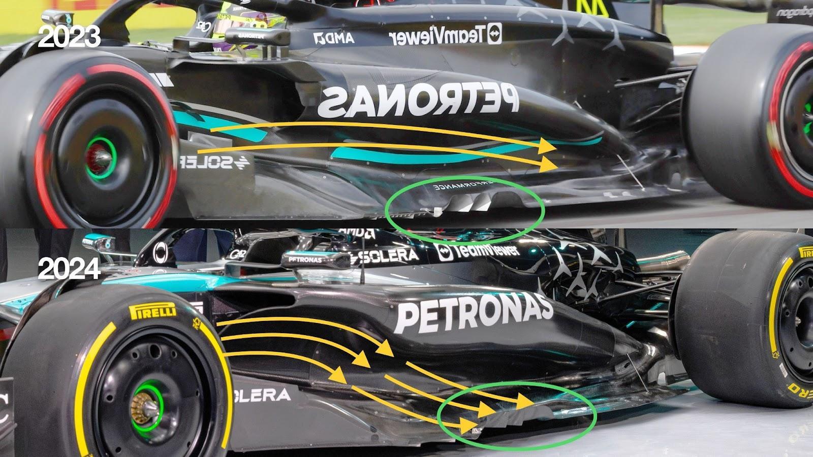
With this style of sidepod, there are much higher levels of mass airflow (yellow arrows) being focused on the side exit vanes (green ellipse) to help scavenge as much of the airflow from that front corner of the underfloor, allowing the diffuser to work on the airflow nearer the centre line of the car.
REAR SUSPENSION
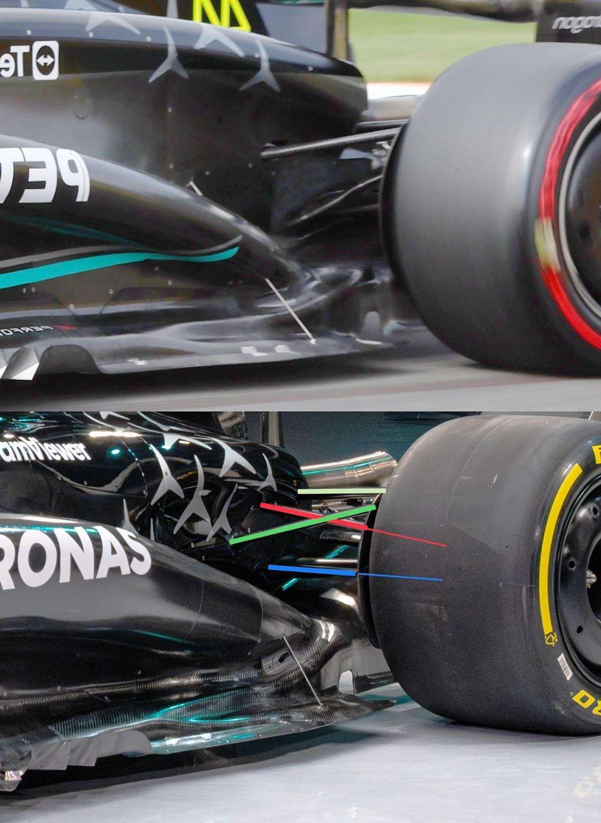
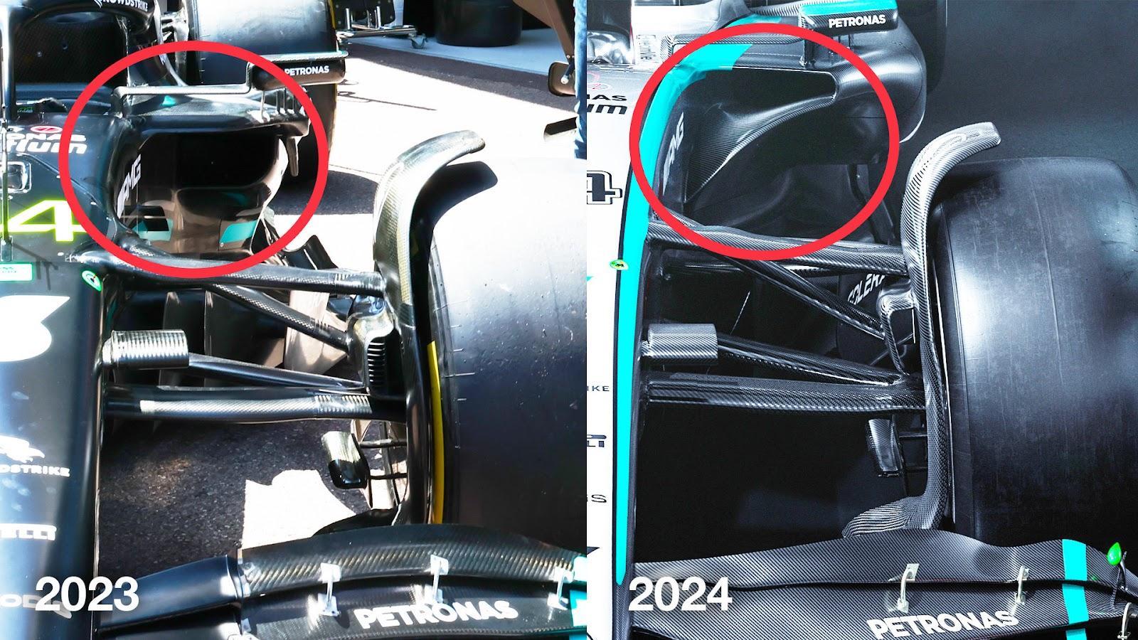
The rear suspension is one of the biggest changes. We have seen what we believed to be the latest Mercedes system on the Aston Martin, which utilises the Mercedes gearbox and rear suspension as part of its customer deal, and these comparison shots of last year’s Mercedes against the 2024 version confirm it has gone to a pushrod system (red highlight) and built in a lot of anti-lift to the top wishbone (dark green highlight) forward leg inner mounting rear suspension geometry.
The rearward leg (light green highlight) is in a similar position to last year.
What I believe is the forward leg of the lower wishbone (blue highlight) is fairly high up.
You want to get the angle between this lower wishbone and the pushrod as big as possible, otherwise the loads in both components go sky high.
As you can see, the location of these components only allow for a very shallow angle. With the pushrod and the lower wishbone theoretical intersection (shown by the thin continuation of highlight above) not really meeting up, there would appear to be something ‘different’ driving the pushrod.
It might just be connected to the upright, but to me, that shallow angle is there for a reason and not just because it’s the easiest way of doing it.
CONCLUSION
I think Mercedes has created something a step better than last year’s car, but again it all comes down to what is underneath.
From what I see, the overbody airflow structure will be more complementary to the underbody airflow structure than it has been over the last couple of years.
Mercedes will be trying hard to make sure its performance makes Lewis Hamilton rue the day he put pen to paper with Ferrari.