Gary Anderson's verdict on McLaren's race-winning F1 upgrade
Since the middle of last year McLaren has brought various development steps for its Formula 1 car and most, if not all, have had a positive influence on performance.
This to me shows a team that has a good technical understanding of its car, both where it is now and what it needs to move forward.
Once again McLaren brought a complete package of developments to Miami last weekend, fast-tracking them from its initial Imola target.
The upgrade was fitted in its entirety to Lando Norris’s car and part of it was on Oscar Piastri’s car.
This was brave of McLaren as it was a sprint weekend with very little time to optimise the set-up around the new parts.
As I have said many times: with any developments, you need to start at the front and work your way through to the rear. That way you get the biggest bang for your buck possible. The unfortunate thing is when you have finished it’s time to start again, it’s a bit like if you were painting the Sydney Harbour Bridge, when one tin of paint runs out, just get another and keep going.
Below you will find how McLaren described the developments to the FIA and my own analysis of each section.
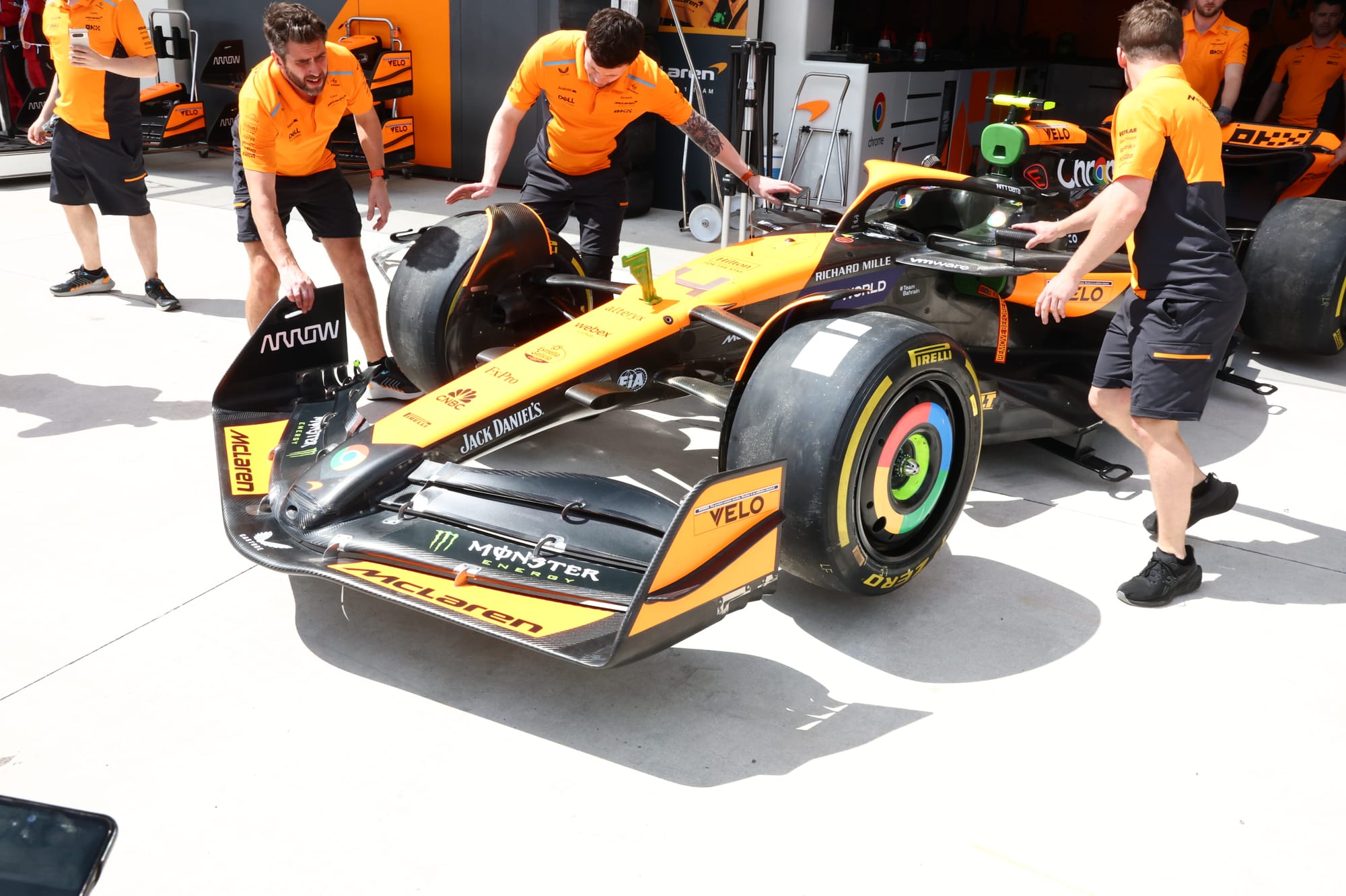
FRONT WING
McLaren says: The completely revised front wing geometry results in a significant improvement of flow control, which in conjunction with the updated front corner and front suspension, results in an overall load gain.
Gary Anderson: Looking at this front wing comparison, there are quite a few subtle changes. Starting with the blue leading edge highlight, we can see that it is flatter, meaning more of the span closer to the ground.
Moving further outboard, from this angle it appears the leading edge of the most forward element, which is highlighted with the green arrow, is raised slightly.
I have marked the trailing edge on the new version in papaya. The older version is in papaya and magenta, under the magenta section is a gurney flap. Usually a team will use a gurney flap in this area if it is struggling for front downforce, especially at low speed. McLaren doesn’t seem to need it on the new version.
The red ellipse is to highlight a change in the nose profile where it meets up with the second front wing element. It now comes that little bit further forward and overhangs the leading edge of that element slightly.
All of these changes should enhance the airflow under the wing so in effect improving the performance of the wing itself and also helping increase the mass flow to the central section of the leading edge of the floor.
FRONT SUSPENSION
McLaren says: The new front suspension geometry has been designed to suit the new front wing and to support and enhance the improvement in flow condition.
Gary says: I would classify this as more of an aerodynamic profile and location optimisation.
As the airflow comes off the trailing edge of the front wing the suspension linkage does its best to realign that flow for whatever aerodynamic components are coming along further downstream.
You don’t want this optimisation to interfere with the performance of the front wing, so really all you're doing is massaging the wake to improve its angle of attack for the sidepod and underfloor leading edge.
Front brake duct and winglet
McLaren says: The new front brake duct has been designed to suit the new front wing and to support and enhance the improvement in flow condition.
Gary says: The front wheel fairing and front brake duct needs to pick up the flow that is being displaced by the front tyre and do the best job possible to return it into the void behind that same front tyre.
This again helps with the airflow to the leading edge of the sidepod and underfloor, reduces wheel turbulence and, in its own right, results in a reasonable drag reduction.
Now for the actual brake cooling duct itself, well that’s another story - it is so complicated. Inside what we see as a simple brake duct, there are ducts within ducts going in all sorts of directions.
The improvement in understanding of the internal airflow of a brake duct from CFD simulation has been such that in years gone past brake ducts would have had 10 times the inlet size they currently have.
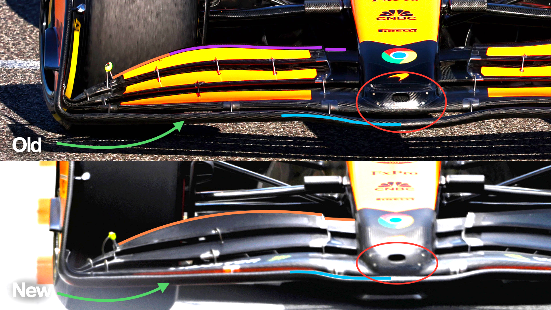
FLOOR BODY
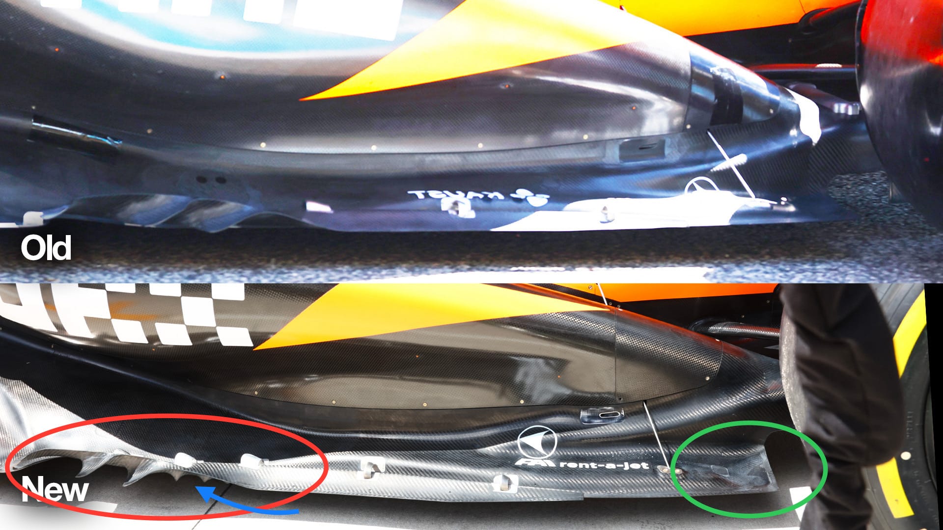
McLaren says: The revised floor has been designed in conjunction with the new sidepod inlet and bodywork to increase the overall load in all conditions.
Gary says: It’s never easy to see the amount of changes that constitute what can be called a new underfloor.
I have highlighted the areas that I think are slightly different but it’s what we don’t see that really makes a big difference.
However in conjunction with the sidepod inlet changes that have allowed McLaren to open up the front corner of the sidepod undercut, these small changes can make the airflow structure around the sidepod much more robust and not so critical to turbulent airflow when in traffic or even just crosswinds.
The red ellipse shows the floor’s front corner scavenging device. These two angled vanes set up vortices which act like a Dyson vacuum cleaner (other vacuum cleaner manufacturers are available) and the energy within that vortex means you get a better bang for your buck when cleaning your carpet, or in F1 terms when you are trying to extract as much airflow as possible out of that area.
The blue arrow shows the end of the leading edge splitters, you can’t really see these in the old version but that may be the angle obscuring it. Getting the end of these splitters and the vortex generators all working together means that this area of the underfloor will be working more consistently.
It looks like there is a small turn-up section at the rear edge of the floor which I have highlighted with a green ellipse.
This will help to connect that area of the floor to what is called the inner tyre squirt. This is the airflow that is displaced when the tyre rotates onto the track surface and is critical to the performance of the diffuser.
It can also be a drag reduction, very similar to the flow around the front tyre. If you can fill in that void behind the rear tyre, you can achieve a reasonable drag reduction.
SIDEPOD INLET
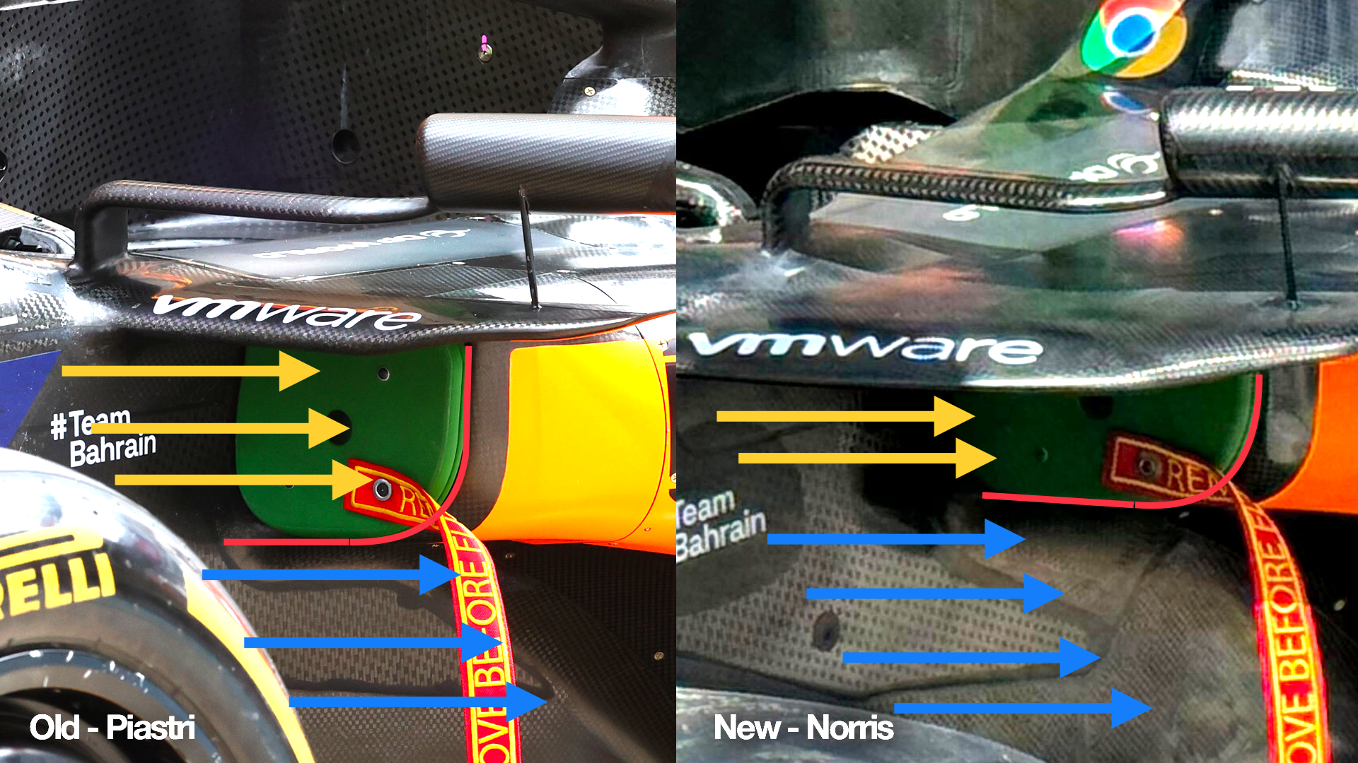
McLaren says: The revised sidepod inlet has been designed to complement the change in onset flow and in conjunction with the bodywork results in an improved flow to the rear of the car.
Gary says: The driving force behind most of these developments has been to reduce and raise the sidepod inlet. As I have said many times airflow used for cooling - which I have highlighted with yellow arrows - is wasted as far as being able to produce downforce from it.
The increased mass airflow through that sidepod front corner undercut (highlighted with the blue arrows) will increase overall downforce from the underfloor by being able to create a better and more consistent vortex sealing system on the outer edge of the floor.
It will reduce the effect on this area from the turbulence from the front wheel, especially at high steering angles, and it is more consistent in how it works when affected by turbulence in traffic.
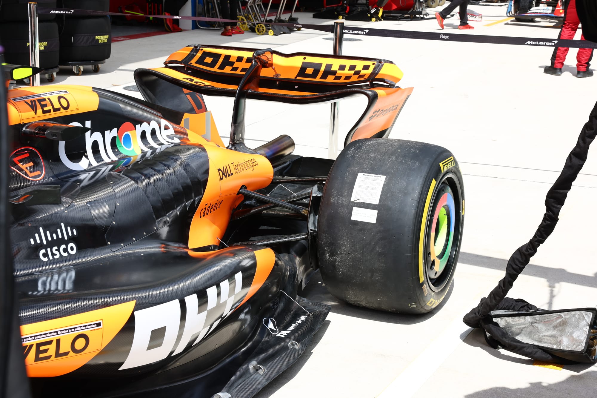
ENGINE COVER
McLaren says: The new bodywork and engine cover results in an improvement in efficiency and flow conditioning in conjunction with the sidepod inlet.
Gary says: The engine cover and coke bottle area have also been optimised to improve the surface flow in line with that sidepod undercut change.
It’s the old story of starting at the front and going through to the rear and along the way a little bit here and a little bit there can bring fairly big returns.
Ideally you achieve that without taking the risk of changing your aerodynamic philosophy. You simply make everything work exactly the same, just that small percentage harder.
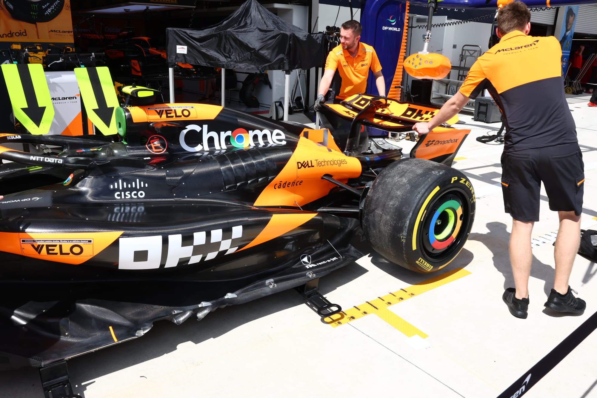
COOLING LOUVRES
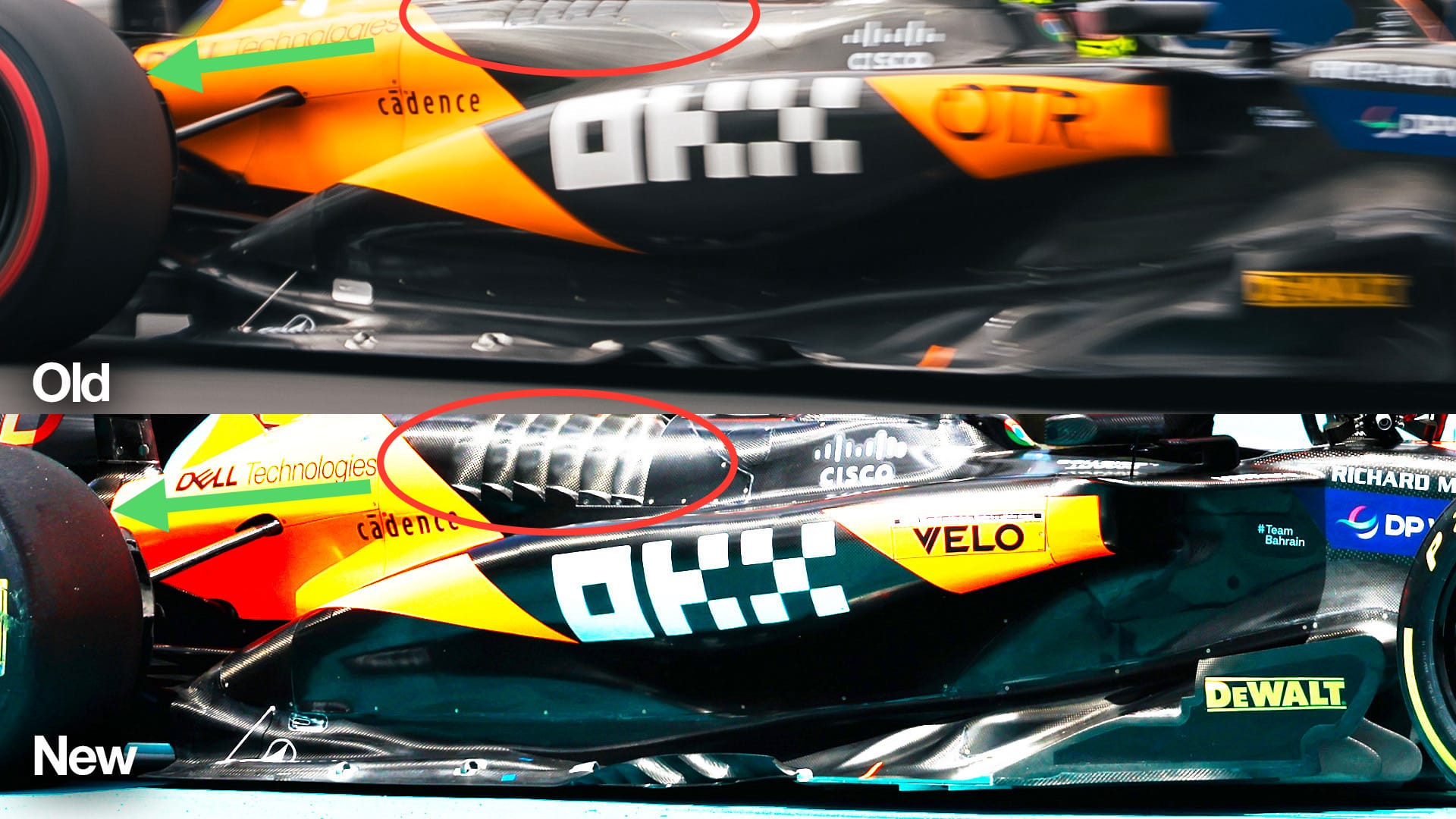
McLaren says: With the revised bodywork shape, the cooling louvre range has been updated, to suit the change in overall flow field.
Gary says: You don’t get the cooling F1 cars require from nowhere.
It looks like McLaren has increased the cooling exit louvre panels highlighted with a red ellipse in line with a reduced inlet size.
The balancing act between these two is never easy. Keeping the inlet as small as possible means the car will be travelling faster when the radiator starts to block up and can’t flow as much air as is being presented to it. So aerodynamically, the smaller it is, the more consistent it is through the speed range. But there is obviously a limit.
This louvre panel will by no means be all of the cooling area, as it also has the twin cannons highlighted with the green arrows which exit out of the rear of the engine cover. However these are what we could call circuit adjustable cooling level exits.
Increasing the exit area increases the pressure drop across the radiator core. You can’t push the airflow through the radiators, you have to pull it through and the bigger the pressure drop the better and more consistent the cooling will be.
But you don’t get something for nothing, bigger exits increase the overall drag level so again it's that compromise word we often talk about.
REAR SUSPENSION
McLaren says: The rear suspension has been updated to suit the change in onset flow condition and to improve load generation through the new rear brake duct geometry.
Gary says: The rear suspension linkage has also been reprofiled, like the front. Optimising these profiles to manipulate the airflow into the areas where you want it will simply improve the performance of the diffuser, beam wing and potentially the upper rear wing.
Minimising the blockage created by these suspension members means that the overall mass airflow will be travelling faster and we all know that the faster the airflow the more potential there is to produce increased levels of downforce.
REAR BRAKE DUCTS
McLaren says: The new rear brake duct geometry benefits from an improvement in onset flow and results in an overall gain in load.
Gary says: Like the front brake cooling, the rear brake duct and its turning vanes are all optimised to suit the revised flow conditions.
The turning vanes on the rear brake ducts are critical as far as braking stability is concerned, as they produce their own downforce onto the upright assembly and in turn the rear tyre.
So although the load is minimal it is immediate and it doesn’t have to go through any lag whilst the suspension is moving, so that small load can have a major stabilising influence when the driver hits the brake pedal.
BEAM WING (circuit-specific)
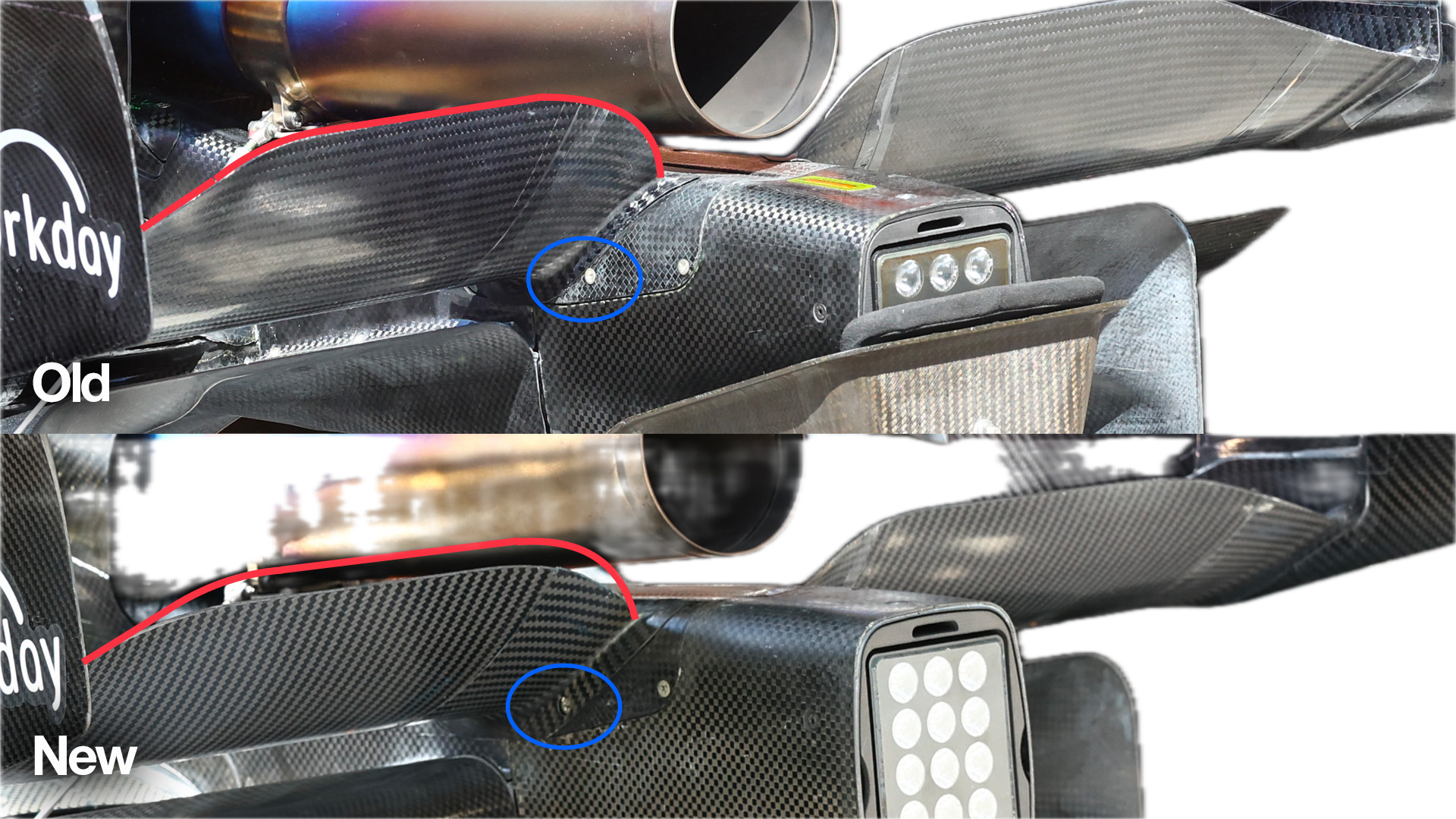
McLaren says: A new, offloaded beam wing has been designed, which trades loading between beam wing and rear wing efficiently, suitable to the track characteristics.
Gary says: As McLaren says, the beam wing is more of a circuit requirement than part of the development package.
It’s very similar in function but just that bit less aggressive, as I have shown with the red trailing edge highlight line.
If you look at the forward fixing to the crash structure (which is highlighted with the blue ellipse) it also looks like the angle has been reduced slightly, to suit the long straights in Miami.
As I said earlier, McLaren seems to know which direction the car development needs to go in to improve its performance but it will take a couple more races to really see if this is a big enough step to put it as a consistent podium contender.
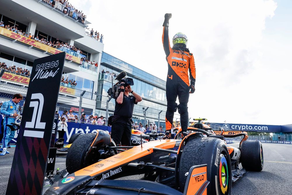
But for now, winning in Miami will for sure give it the motivation to keep pushing.