Gary Anderson: Red Bull sidepods show likely Mercedes flaw
Countless hours of windtunnel and CFD research are invested in defining the best geometry for a Formula 1 car’s bodywork surfaces. But it all starts from an aerodynamic concept, or what you might call a vision.
No team starts with a rectangular block of modelling clay and carves out the car’s shape from there. It’s all about where you start that dictates where you end up, so the early vision is critical to the end result and, in turn, the car’s performance.
It’s impossible for any team to work through all the iterations that we have seen created from these new aerodynamic regulations. You might have had a look at a few of them, and teams have referred to doing that, but at some point in time you have to buy into one of them and optimise that solution.
The car’s ultimate performance is the sum of its total parts. No one component or area is all-important, but some do take priority as they offer the biggest potential rewards.

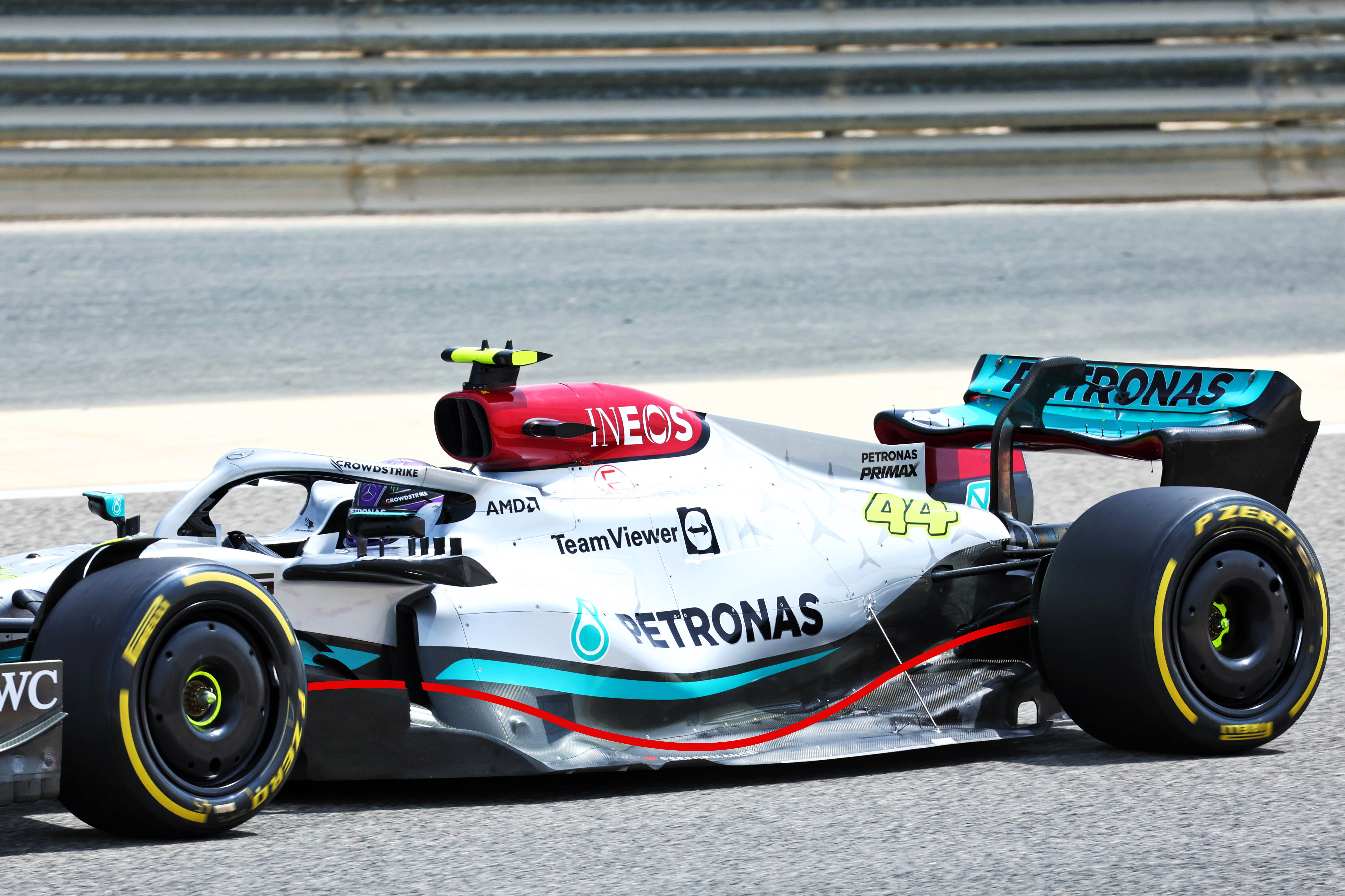
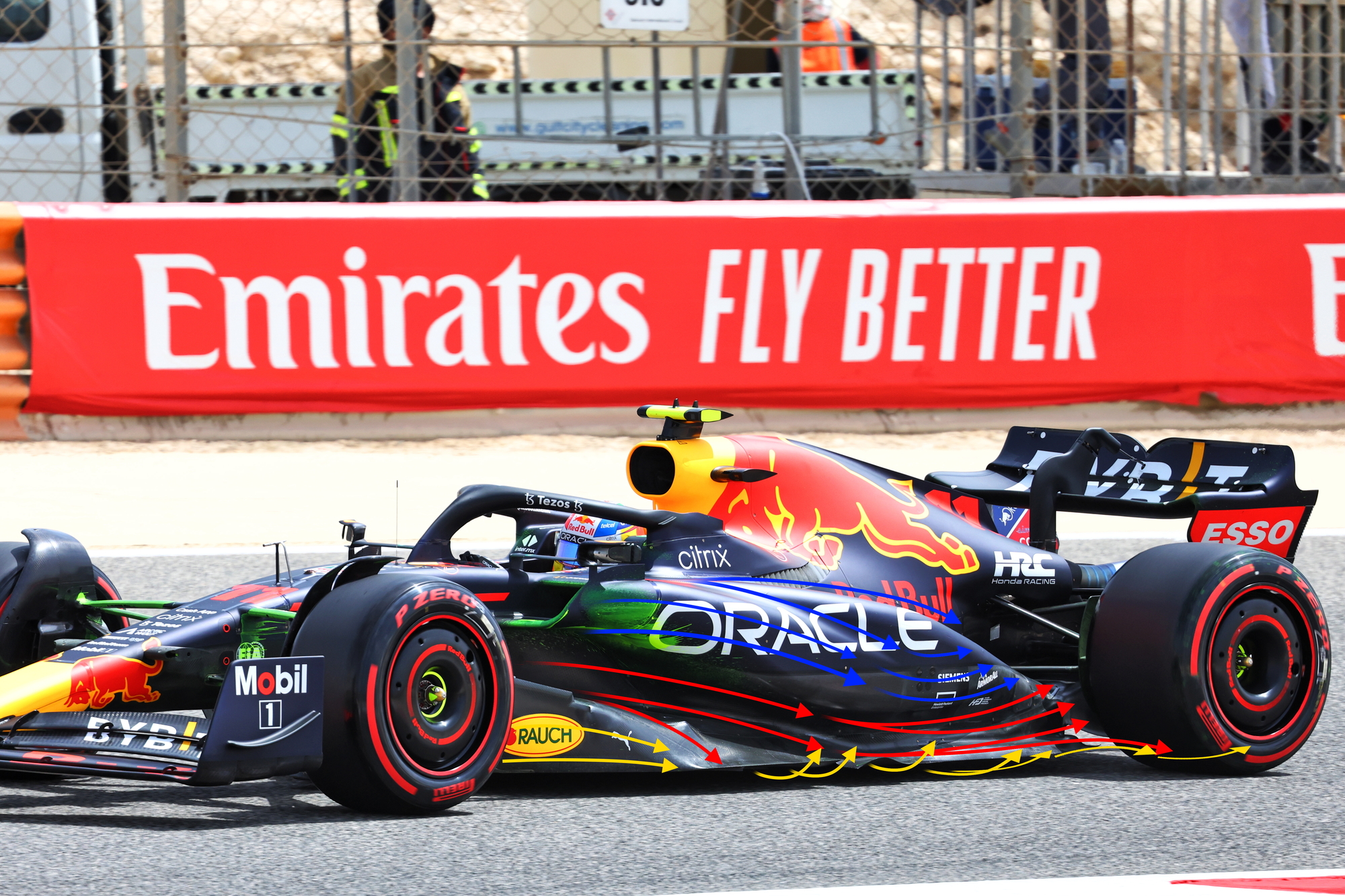
A couple of weeks ago, we compared the Ferrari and the Aston Martin sidepod concepts. Now, we can take a look at the Red Bull compared to the Mercedes in a similar way.
As can be seen from the two side views, we have created a section through the undercut area of the sidepod. It’s difficult to do on the Mercedes because it doesn’t really have an undercut. But with these two very different concepts, or as I like to call them visions, the smaller details are what really matter.

Firstly, if the floor area is important to the overall downforce generated by the underside of the car and most teams have gone for as long a wheelbase as possible to achieve this, then why is the Mercedes floor in plan view smaller than the Red Bull?
We can see from the leading edge of the outboard splitter/bargeboard on the Mercedes that it is very similar in location to the Red Bull. However, the leading edge of the floor is further rearward. This does get it further away from the turbulence of the front tyre wake but that is not as important as in the past when you were trying to maximise the space for the bargeboards.
We can also see the leading edge of the other splitters peeking out of the front, whereas the Red Bull’s splitters are inside the leading edge of the floor.

The height and width of this leading edge is critical to how much mass flow goes under the car. This is indicated by the purple arrows. But it’s not as critical to the consistency of that mass flow and how the leading edge splitters distribute that flow.
Some of it will be turned outwards to help set up the vortices (brown arrows) that help seal the sides of the floor. Some of it will be pulled through under the central area of the floor by the diffuser, increasing its speed and in turn generating a lower pressure under the car pulling it down towards the ground.
All the rest of it is about managing that flow and any flow separation problems that are created by asking too much of any part of that airflow. The airflow is not solid so, depending on what you are trying to do with it, it will compress and/or expand to a certain degree. If you are trying to compress it too much it will just find the easiest route, if you are trying to expand it too much it will just detach itself from the surface you are asking it to follow.
If that is happening in the windtunnel then it will be a lot worse when you hit the track. Although you go through a ride-height sequence in the windtunnel to define the aero map, the data gathered at each ride-height point is when the model is in a steady state, it is nothing like how the car runs on the track when it is constantly on the move because of bumps or even just the track surface never being as flat as the windtunnel belt.
As clearly shown by the green arrows, the upper floor area on the Red Bull is much wider than on the Mercedes. You also see with the silhouette of the upper part of the sidepods that Red Bull has an upper section to help contain that flow. This is what we call the undercut.
Because there is a lower and upper surface and forces generated on these surfaces by the airflow speeding up should to all intents and purposes cancel each other out, it means that you can use this style of sidepod design to alter the direction of the flow to suit your needs further downstream.

Not only does Mercedes have less area and no upper section to contain it, so no undercut, but it also has the radiator inlet in the middle of that flow area.
I would question that as a concept for delivering consistent flow to the underfloor. On any car, the radiator flow will change with speed. As the car goes faster, the radiator just can’t handle that much mass flow so it will start to generate blockage, and this excess flow will spill around the leading edge of the inlet.
That spillage will be pulled towards the edge that has the lowest pressure. In this case, that’s under the car into the underfloor.
It could be said that extra flow at high speed going under the floor will reduce the chance of the central part of the underfloor stalling and generating porpoising. But it lacks consistency and will be very difficult to optimise for all conditions and differing cooling requirements. For example, changing the radiator exit ducts to increase or decrease the cooling level and the underfloor performance will alter with that change.

Again, we can see how the sidepod with its very defined profile change on the Red Bull could direct the airflow around the rear tyre (yellow arrows). Connecting this flow up to that displaced by the rear tyre and the lower tyre squirt (magenta arrows) will help with flow consistency. As there is a low-pressure area behind the rear tyre, which this flow will be pulled into, it should also reduce drag generated by these very large tyres.
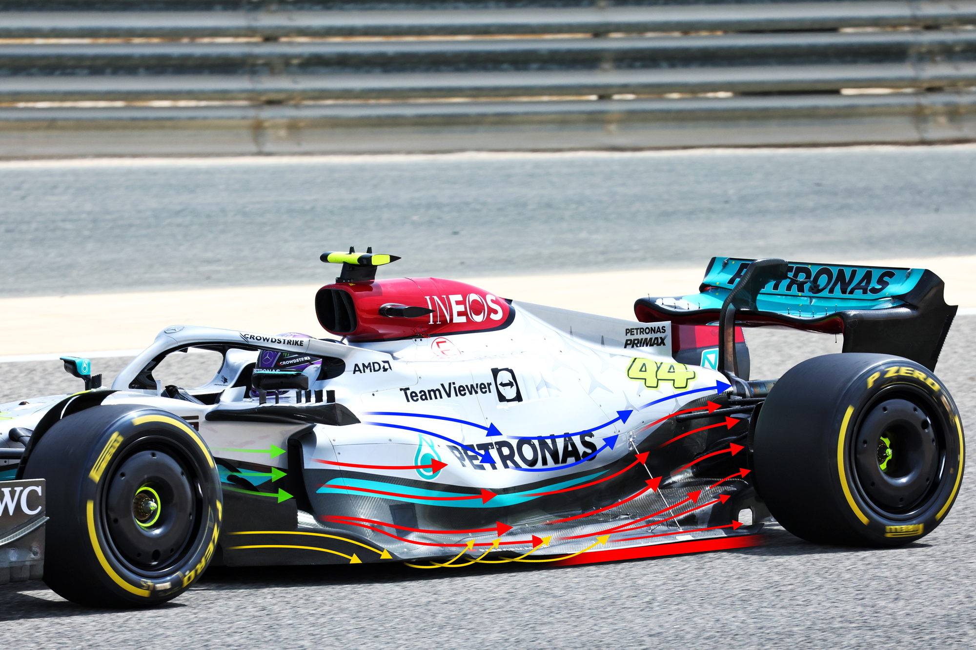
The Mercedes will do the same, but by having the sidepods (small as they are) angled inwards as they come upwards from the top surface of the floor, it allows that flow simply to get pulled into the Coke bottle area. This means it is not doing as much to influence the airflow over the top surface of the floor, which in turn will influence the airflow on the underside of the floor.
It is the sum of the parts that makes up the overall performance of the car, but as we all know the underfloor with these new regulations is very powerful so it needs to get priority. The wing mirror mounting system that Mercedes has created and the sidepod surfaces may need to work hand in hand to comply with the regulations as far as how many body profiles you can use in this area.
However, the reverse wing-mirror mounting system will generate lift in its own right, so using vortices generated by this component to help the floor seems a bit far-fetched. Yes, they will generate downwash but with no sidepod behind them that downwash will simply get pulled into the Coke bottle area.
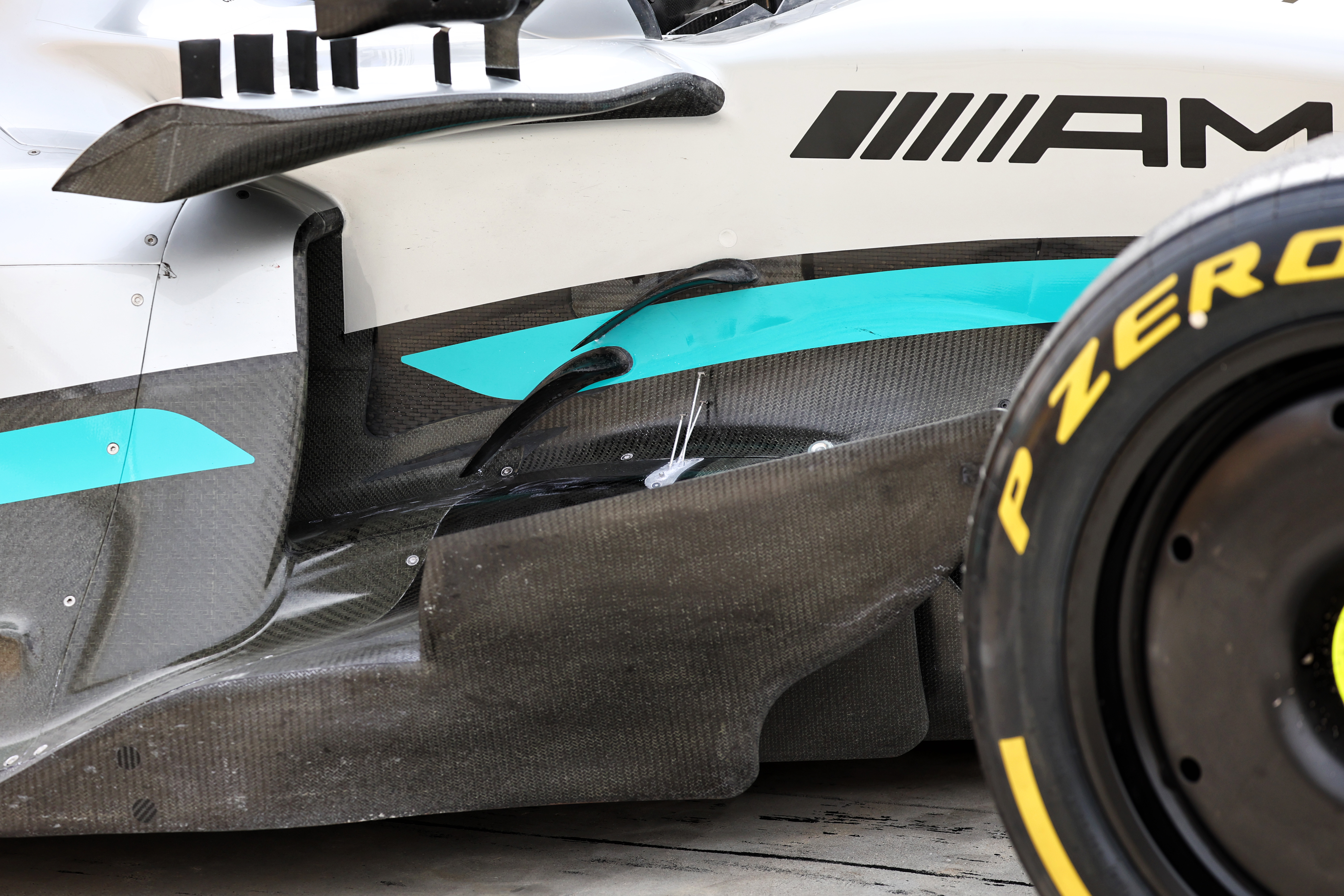
From my point of view, the main areas on the Mercedes I would be focusing on are the red arrows. First of all is the radiator inlet position, which for many years on every car has been getting more and more detached from the leading edge of the underfloor by the undercut sidepods to reduce that radiator duct spillage from being pulled under the car. For these ground-effect cars, it is no different, it’s just more important as the pressure under the car should be much lower than in the past.
Secondly, the red arrows from halfway down the outer edge of the floor to the leading edge of the rear tyre are also suspect. If the front of the sidepod doesn’t have the power to generate the outwash to a level that helps set up the vortices that help seal the floor, then you have to achieve that in some other way.
The car’s ride height becomes much more critical to its performance. A millimetre of rear ride height could generate tenths of a second worth of laptime. But the problem is that another millimetre can generate massive porpoising, so it’s very difficult to get the best out of the underfloor especially in the area of the red bar I have put along the edge of the Mercedes floor.
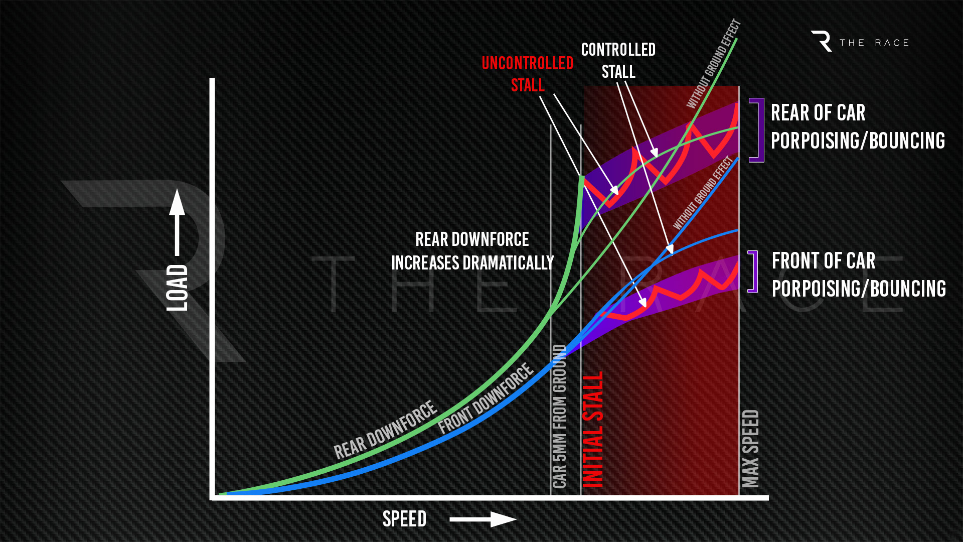
Porpoising is generated when the underfloor surface stalls. If that stall is big enough that the numbers drop a lesser value, then the car will porpoise or will be seen to be bouncing. This stall then reattaches when the car rises up and the process starts all over again. On this graph I have called it an ‘uncontrolled stall’.
The trick is to still have a stall that will also reduce drag but for the numbers never to drop to a lesser value – just not increase by as much. On this graph I have called that a ‘controlled stall’ and if you can achieve this then you can run a lower ride height at lower speeds, generating more downforce for medium-speed corners.
This stall can be set off by simply overworking the underfloor, or if you are close to that threshold a simple bump will start it and it will then continue until the driver slows down and the car’s ride height increases.
It will be interesting to see which direction Mercedes takes to get out of its current hole. Some of it can probably be controlled with damping and ride-height control but normally you pay the price for that in other areas like being unable to cut the kerbs or tyre grip feedback during braking or accelerating.
All is not lost – yet – but the first thing you have to do as a team is identify the source of the problem. If you can do that then you can rectify it.
But the clock is ticking.