Gary Anderson's in-depth analysis of 2026 Aston Martin F1 car
Aston Martin finally hit the track at Barcelona late on Thursday afternoon. It was an inauspicious start, as Lance Stroll only managed four-and-a-bit slow laps before grinding to a halt. We don't know what the problem is, but that's what pre-season testing is all about: finding and fixing your problems so you're ready to go to Melbourne and get a result.
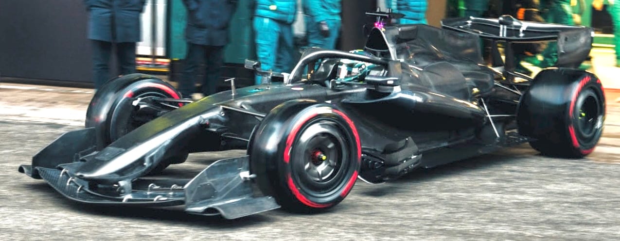
But when the Aston Martin AMR26 rolled out of the garage, it caught the eye more than any other car.
This is Adrian Newey's first Aston Martin F1 car after two decades at Red Bull, and this new adventure seems to have inspired him as, from what I've seen, it looks like a good interpretation of the new regulations. And to think the majority of it comes from just a man with a pencil and a drawing board...
On Thursday, I gave you my initial thoughts from what we first saw on the car but, with a few more fairly grainy images that we've enhanced as best we can, there's now enough detail to get into. And just as the airflow across the whole car is set up by the front wing and nose, I'm going to start at the front.

The nose-to-front-wing hangers highlighted in red attach to the second element of the front wing. This is the most efficient way of doing it, as it means the structural part of the nose can be shorter. If you consider the front wing's vertical load, its centre point would be in this area. If you mount it by the front element, which most teams have, then the peak load will be behind the mountings; this puts a torque into the mounting system.
However, it does mean that with these new active aerodynamic rules that you will probably only be able to back off the third element when you activate straight line mode. The forward element is mounted to the second element with the hangers highlighted with the green ellipses, so they would be rigid. The third element is mounted to the second element with the hangers highlighted with the yellow ellipses, so they will have a pivot allowing the third element to back off when requested. The jury is still out on which solution is the best.
The front wing endplates are fairly simple and don't have any upper vanes as some other cars have, for now. However, the outer tunnel, highlighted in light yellow, is as big as any I have seen and appears to reduce in height but gain in width going rearwards. This tunnel will reduce the sensitivity of this very wide footplate when it gets nearer to the track surface. Think of that sensitivity problem being similar to the porpoising of yesteryear when the cars started bouncing because of a lack of control of the ground effect aerodynamics.
The nose is also fairly benign. This large radius highlighted in white on the front outer corners blending into the sides to the upper surface will entice airflow to spill off it and travel around the sides of the nose into the void under the nose. There, it will meet up with the airflow that passes through between the wing mounting pillars highlighted in red and together head off to the leading edge of the underfloor.
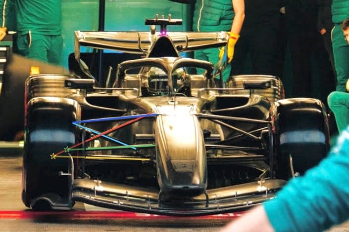
And now for the more interesting part: the front suspension. Yes, it's similar to most in that it is a double-wishbone system with a pushrod-operated inboard springing and damping mechanism. But Aston Martin has pushed the limits just that little bit further on the overall packaging.
The highlight colours are different components that make up the double wishbone system. The top wishbone forward leg is dark blue, the rearward leg light blue, the pushrod red. What I believe to be the bottom wishbone forward leg is green, and the trackrod yellow.
The lighter extension of those colours going out to the coloured stars is why I say 'what I believe to be the bottom wishbone forward leg is green', because the stars are showing where I believe the intersection with the pushrod would roughly be. If it was at the yellow star then it would be too far into the wheel; however, the pushrod could be driven from the upright and not the bottom wishbone, so in reality it could then be either of those colours that is the forward leg of the lower wishbone.
Either way, as you can see with the upper wishbone forward leg inboard mounting, the complete front suspension system is mounted as high as possible within the current chassis rules for the upper surface profile of the chassis structure.
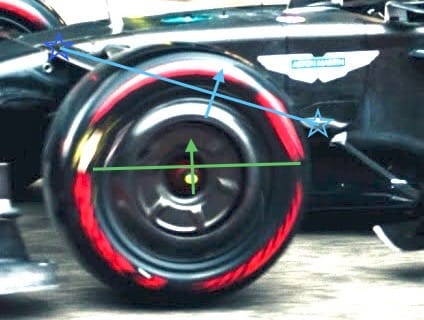
However, the inboard pickup for the top wishbone rearward leg is much lower and further rearward than most others. This dark blue star shows the inboard pickup for the forward leg, the light blue star marks the inboard pickup for the rearward leg, and the light blue line connecting them shows the inboard pivot line. The light blue arrow shows the upper wishbone direction of travel as the ride height reduces with speed or under braking or when the car rolls.
The green line is a guesstimate of the lower wishbone pivot line, while the green arrow is its direction of travel as the ride height reduces with speed or under braking or when the car rolls.
If you're looking for in-depth F1 coverage this pre-season, The Race Members' Club is the place to be. Join today to claim a seven-day free trial
Ride-height reduction with speed will happen depending on the vertical stiffness of the car. There will also be a slight movement with roll, but with this amount of anti-dive there won't be much, if any, movement under braking. It's only when you come off the brakes that the car will get back to its proper ride height for the aerodynamic load at the speed it is traveling at.
In effect, this suspension layout will increase the caster with speed, which can give more straightline stability and/or decrease caster as the speed reduces. This will reduce the steering load for slower-speed corners, giving the driver more steering feedback.
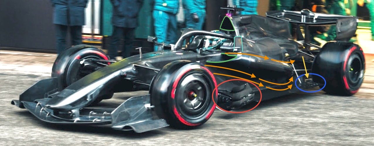
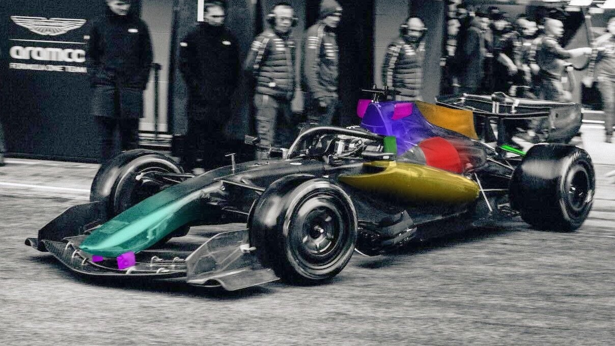
Moving to the middle of the car, the side view is where you start to see the aerodynamic differences mount up. The sidepods are reduced in cross-section. I wouldn't say they are narrow or 'zero' sidepods, but their volume runs more or less in line with what the airflow structure around them would want to do.
I have highlighted this with the orange arrows. Basically, after defining that shape, you then open up an inlet in the area that has the least negative effect on the overall sidepod flow structure. Aston Martin has returned to the 2023 Adrian Newey Red Bull-style duckbill inlet, highlighted in green.
It also has a vertical fin mounted beside the start of the headrest/driver's helmet. This is to contain and realign the airflow that is forced around the bluff leading edge to the headrest. Doing this means less negative effect of that orange highlighted overall airflow structure.
The airbox inlet, highlighted in green, also adds to the overall cooling flow volume. The area below that inlet and the top of the driver's headrest is aggressively undercut, which will reduce the potential of driver helmet buffeting. The engine cover volume above the actual engine is quite small, so I don't think that there are many of the cooling radiator requirements mounted that high up. A lower centre of gravity for any car is always positive.
The bargeboard area inside the red ellipse has the now-customary louvre sections drawing airflow from inside to outside of the overall component. When the regulations were introduced, this component was defined as a vertical surface starting wide at its most forward point and getting narrower as it went rearward. The intention was to generate inwash, or at least reduce that dreaded outwash. With these louvres and their position, inwash is the last thing they will produce.
Aston Martin also have the louvres, which are highlighted with the blue ellipse, in the floor section in front of the rear tyre. I can't see them in detail, but I believe they will connect the airflow on top of the floor in that area with what is called the outward tyre squirt. This is the airflow that is displaced when the tyre rotates onto the track surface. Doing it this way will reduce the tyre squirt going inboard.
It looks like Aston Martin has also discovered the potential opening in the diffuser sidewall, which I have highlighted above with a yellow arrow. This is what is being called, by some, a blown diffuser - basically, introducing high-energy airflow into an area where the airflow is getting a bit tired.
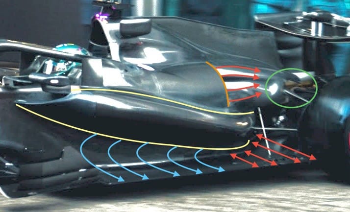
A close look at the sidepod shows how little volume there is to store any radiator cooling cores. I have highlighted this area, top and bottom, with the yellow lines. You can also see how wide and long the leading edge undercut really is, with the light blue arrows showing how it comes from that front corner of the sidepods and gets a little narrower, forcing some of that airflow outwards.
It then opens up abruptly, which is highlighted with the red arrows just where the high pressure in front of the rear tyre needs to be relieved. This abrupt opening will entice that displaced airflow to go inside through what is called the Coke bottle area. Increasing this flow volume reduces tyre drag and improves the performance of the diffuser and rear wing, a win-win situation.
Now we come to what looks like a huge engine cover cooling outlet, which I have highlighted the trailing edge of with the orange line. Yes, it is rather large but part of that is because the inner surface of that outlet duct is basically a 'limpet' fit to whatever is housed under that section of the engine cover. This makes the outlet look bigger.
Also, it is further forward than the 'cannon' outlets (which aren't small) that we see at the rear of most other cars' engine covers. Being more forward means there is more time for the hot cooling airflow, which is highlighted with the red arrows, to mix with the free-stream airflow before it gets to the rear wing. These forward outlets don't require any major rear outlets where other cars have them in the area of the green ellipse.
My motto is don't fool yourself with the car's overall efficiency and downforce numbers by not running with adequate cooling for those hot races. Start there and when it's colder, you can always use a bit of duct tape on the radiator cores until you get your cooling balance and overall requirements sorted out.
The rear suspension layout is interesting. Yes, it's a top wishbone and either a lower double-link or wishbone and toe link system, with a pushrod-operated inboard spring and damper mechanism, but it's the positioning of everything that is significant.
For a closer look I have cropped the above picture. This reduces its quality but it gives us more of an idea of that layout.
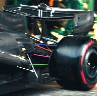
The top wishbone forward leg is highlighted in dark blue and the rear leg light blue. One of the interesting features is how high the inboard end of the rear leg is mounted. It looks like it mounts on the central rear wing pylon. So what does that achieve?
To get a decent level of anti-lift on the rear suspension, it's the difference in relative heights of the inboard mounts of the top and/or bottom wishbones that matters. By having the rear leg inboard mount higher, it means that the forward leg inboard mount can also be higher. Basically, it gets that forward leg out of the way and should be better structurally as it will go nearer to the top surface of the gearbox outer surface, as opposed to it being in the middle of the side panel of that structure.
The pushrod is highlighted in red, the driveshaft shroud in magenta, and the lower wishbone - or link as it might be - in green. Again, this green link goes forward a long way and might even mount onto the engine, or at least the engine-to-gearbox interface.
I have highlighted the floor stay with a white arrow that is in front and inside of the rear tyre. However, there is another stay or link further rearward, again highlighted with a white arrow. It seems to mount inboard just between the top wishbone inboard mounts. I don't think it is anything to do with the suspension and it could just be a diffuser stay.
It's great to see a car that is a bit different, but that doesn't mean it's better than the others. However, it shows some lateral thinking and demonstrates that there are quite a few ways to achieve the same end result.
Adrian has been very good at that in the past, but today's cars are not the work of one person, so there will be many very intelligent brains who have contributed to what we are looking at. But the reality is that you still need one captain to decide in which direction the ship is travelling in, and that person at Aston Martin is Adrian Newey.